-Indicator Light Feature
Material And Design Specifications
As an industry pioneer, Advance Automation was the first company to utilize reed switch technology in conjunction with a cylinder. Today, the company offers six different magno reed switch models:
-LS10A - Original model; low profile; light duty applications
-LS10 - Light duty applications
-LS30 - Utilize as NO and NC; light duty applications
-LS11 - Green L.E.D. indicator light; light duty applications
-LS21 - Triac; A.C. only; orange neon indicator light; heavy duty applications
Light duty applications include programmable logic controllers and computers. Heavy duty applications include devices such as solenoid valves, contactors, and lamp loads exceeding 10 watts.
Reed Switch
Switch Description
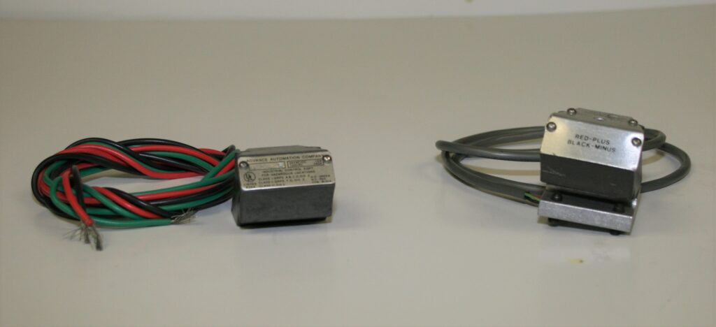
The aluminum switch housing contains a reed device, which consists of two overlapping reed blades of a ferromagnetic material. These blades are supported in a hermetically sealed glass tube and encased in epoxy resin in the housing. Each reed blade connects to its own exterior wire lead.
Switch Actuation
All the reed switches that Advance Automation offers operate in the same manner. The groove on the piston is machined deeper to accept a magnet strip. The switch actuates when the magnet on the piston passes under the reed device. Because the reeds are ferromagnetic, the opposite ends assume opposite magnetic polarity when brought within the influence of a magnetic field. The reed blades will then do one of two things:
1.Close (NO - normally open switch)
2.Open (NC - normally closed switch)
Switch Applications
Use it for automatic cylinder cycling, light indication, cylinder programming and sequencing, trip timers and counters, multi-position signaling, and many other applications. A switch may be connected to a programmable logic controller, a PC, or a relay. The operation of the switch can be repeated millions of times at extremely high speeds. The mechanical life of a switch is 10 to 100 million cycles. The electrical life of a switch, when used within the recommended guidelines, exceeds 2 million operations.
Switch Ratings
Do Not Exceed Switch Rating.
Caution
Limit switches can be destroyed by a very brief contact across line voltage, such as brushing a wire against conduit. DO NOT CONNECT WITH A LIVE CIRCUIT. Turn on power only after you are certain that the switch is connected in series with a properly rated load.
Switch Testing
All switches have been factory tested. If field testing is desired, the testing device must coincide with all switch data to prevent switch failures due to testing.
Facts
LS10A & 10 -- These switches have reeds only. To protect against contact deterioration, a contact protection circuit may be required.
LS30 -- This switch contains a reed only with 3 leads. They are green (NO - Normally Open), red (NC - Normally Closed) and black (common). To protect against contact deterioration, a contact protection circuit may be required.
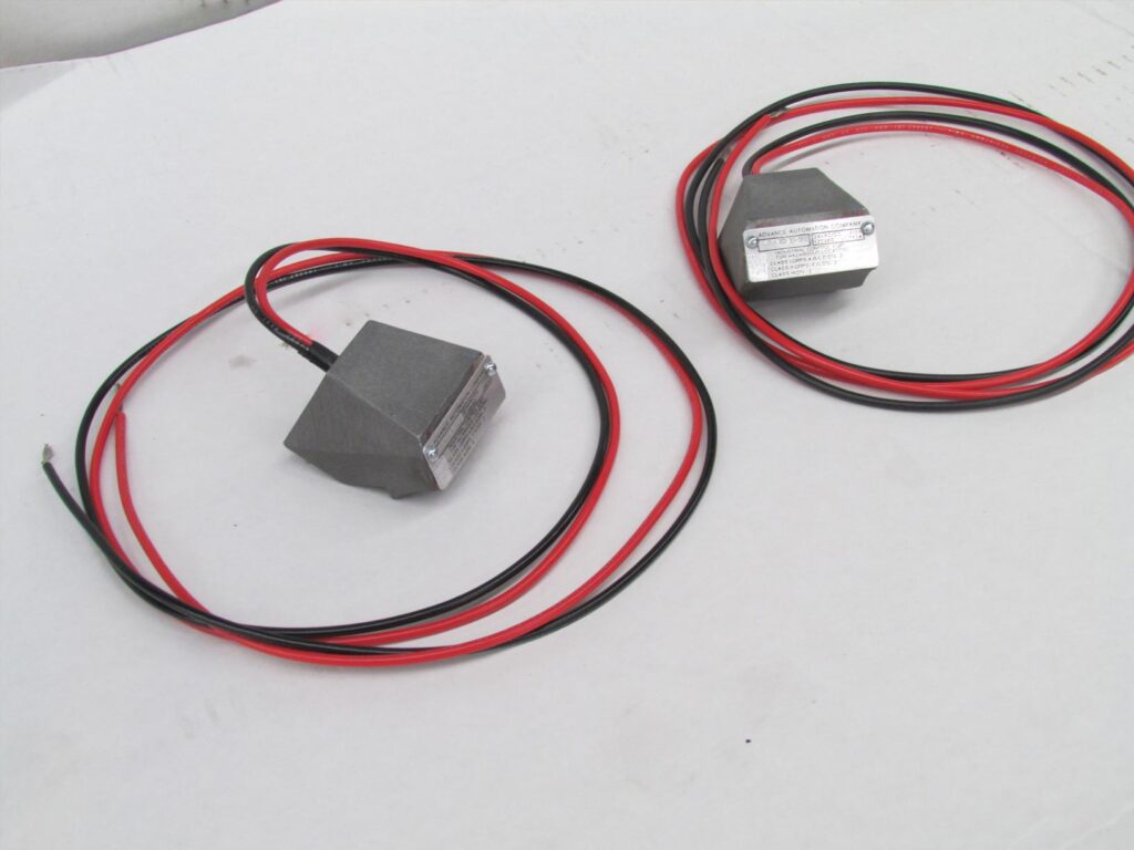
LS11 & LS21 Indicator Light Reed Switch
In addition to all the industry leading features and benefits of the popular LS10 and LS20 switches, these models incorporate lights to show the on/off status of the switch.
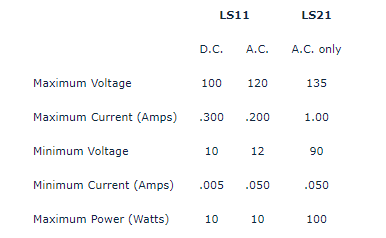
LS11 -- A two (2) wire device intended for lower level D.C. voltages. The LS11 is excellent for use with solid state logic systems and programmable controllers that require 12 to 30V D.C. inputs. A green L.E.D. provides the illumination (see specifications and wiring).
LS21 -- A three (3) wire device intended for 110-120 A.C. operation at up to 1.00 AMP. An orange neon bulb provides the illumination (see specifications and wiring).
Models Available: These are not UL listed.
LS11L LS21L
LS11R LS21R
Specifications for LS11 & LS21
Note: To find power in watts, simply multiply current times voltage (i.e.: Power = Volts x Amps)


